
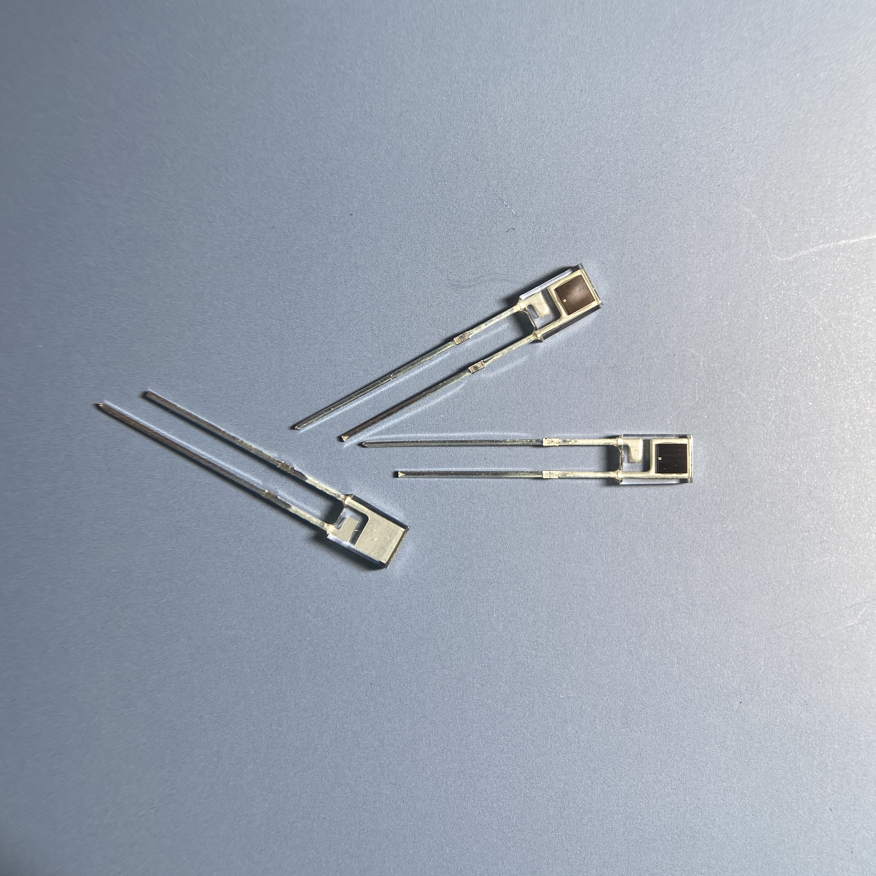
Why "940nm IR LED" Is Not a Specification
Most component requests begin with a wavelength: 850nm, 940nm, 1050nm. That number describes the spectral region, not the device. Two emitters can both be ordered as "940nm infrared LED" — one delivers a narrow beam at high intensity for a beam-break sensor, the other a wide, even wash of light for a remote control receiver. Same wavelength, different device.
Jiangmen City Yiyang Infrared Semi-conductor Co., Ltd (Yiyang Optoelectronics YY) has manufactured infrared emitting diodes, photodiode receivers and remote-control receiver modules in Jiangmen, Guangdong for over 13 years, with a daily production capacity of 600K pieces and exports to more than 40 countries. Over that period, the specification lines that generate the most rework are the ones that name a wavelength and stop there.
A complete emitter specification has five independent parts, and they must be read together:
- Peak and centre wavelength — what colour of infrared, and how tightly controlled.
- Radiant intensity — how much optical power leaves the package in the forward direction.
- Viewing angle — how that power is spread.
- Forward voltage and forward current — what the drive circuit must supply.
- Package and lens — the geometry that produces the first three figures.
1. Peak Wavelength, Centre Wavelength and Bin Codes
An infrared emitter does not emit a single wavelength. It emits a band with a peak, and the datasheet normally gives both the peak wavelength (the maximum of the curve) and the centre wavelength (the midpoint of the half-power band). For a typical 940nm emitter these sit close together; for a 660nm visible-red chip they differ more noticeably.
| Nominal wavelength | Typical application | Notes |
|---|---|---|
| 850nm | Security cameras, beam-break sensors, high-power illumination | Higher radiant output per watt; faint red glow visible to the eye |
| 880nm | Optical switches, encoders, general sensing | Compromise between output and invisible operation |
| 940nm | Remote controls, IR receiver modules, proximity sensing | Almost invisible to the eye; the standard for consumer remote control |
| 660nm / 905nm pair | Pulse oximetry (SpO₂) | Two chips in one package; the wavelength pair is fixed by the measurement principle |
Two details decide whether a delivered batch behaves as designed. Wavelength shifts with temperature and current: the peak moves toward longer wavelengths as the junction heats, typically by 0.2–0.4nm per °C for an AlGaAs/GaAlAs device. An optical filter aligned to a nominal 940nm must therefore be specified with a passband wide enough to cover the drift over the operating temperature range, or the system will lose signal as it warms. Wavelength varies wafer-to-wafer, which is why manufacturers sort finished parts into wavelength bins and why a buyer should specify the bin rather than the nominal figure. A request for "940nm ±10nm" is a bin request; a request for "940nm" is not.
2. Radiant Intensity and Radiant Flux
Two units appear on emitter datasheets and they are not interchangeable.
| Quantity | Symbol | Unit | What it measures |
|---|---|---|---|
| Radiant flux (power) | Φe | mW | Total optical power emitted in all directions |
| Radiant intensity | Ie | mW/sr | Optical power per unit solid angle in a given direction |
| Irradiance | Ee | mW/cm² | Power landing on a surface — what the detector actually sees |
The figure that matters for most designs is irradiance at the detector, which depends on the emitter's intensity, the distance and the alignment. A common sourcing error is to compare two emitters on radiant intensity alone. A narrow-angle part can show a much higher intensity figure than a wide-angle part while emitting the same total power — it simply concentrates that power into a smaller cone.
When specifying, state the measurement condition. Radiant intensity is normally quoted at a defined forward current (commonly 20mA, 50mA or 100mA) and a defined temperature (usually 25°C). A figure quoted at 100mA cannot be compared with one quoted at 20mA without reference to the derating curve.
3. Viewing Angle: The Half-Angle Convention
Viewing angle is quoted as 2θ½ — twice the angle at which intensity falls to half of its on-axis value. This convention matters because a part described as "30 degrees" is a ±15° cone, and the energy outside that cone is not zero, just lower.
| 2θ½ (half-angle) | Beam character | Typical use |
|---|---|---|
| 10°–20° | Narrow, concentrated | Long-range beam-break, optical encoders, collimated sensing |
| 30°–45° | Moderate | Proximity sensors, reflective optical switches |
| 60°–120° | Wide, diffuse | Remote-control transmitters, general illumination for sensing, oximetry |
The angle is produced by the lens geometry of the package, so angle and intensity are two readings of the same physical fact. When a design needs a specific irradiance at a specific distance and offset, the correct approach is to specify the required irradiance and the geometry, and let the supplier propose the package — not to specify an angle and then discover the intensity is wrong.
For wide-angle parts, on-axis intensity is lower but the total emitted power may be higher. For pulse oximetry, wide and even illumination over the photodiode window is the objective, not a collimated beam, which is why oximetry emitters are specified by the uniformity of the illuminated area rather than by a narrow angle.
4. Forward Voltage and Forward Current
These two define the drive circuit and the thermal budget.
| Parameter | Typical value | Design consequence |
|---|---|---|
| Forward voltage Vf (940nm, 20mA) | 1.2–1.6 V | Lower Vf means less heat per unit current |
| Forward voltage Vf (850nm, 20mA) | 1.4–1.8 V | Higher bandgap material, higher Vf |
| Continuous forward current | 20–100 mA depending on package | Sets the required drive and thermal path |
| Peak forward current (pulsed) | Often 1 A with low duty cycle | Allows high instantaneous output without overheating |
| Power dissipation | Derived from Vf × If | Limits the LED current in a given package |
Three practical rules apply. Pulsed drive is the standard way to increase output. A remote-control transmitter commonly drives the LED at high current with a low duty cycle, which raises instantaneous radiant intensity while keeping average power and junction temperature acceptable. The specification must state whether the quoted intensity is under continuous or pulsed conditions. Derate with temperature. Maximum forward current falls as ambient temperature rises; a design that runs the LED at its rated maximum at 25°C will exceed the rating inside a closed enclosure. Series resistance and Vf spread interact. If Vf varies across a batch, a simple resistor drive produces varying current and therefore varying output; a constant-current driver removes that dependence and is why it is preferred for any application where output consistency matters.
5. Package, Lens and Lead Form
The package is what converts a chip's output into the intensity and angle figures above. Standard families:
| Package | Character | Notes |
|---|---|---|
| 3mm round through-hole | Compact, clear epoxy | Long-lead options available for flexible mounting depth |
| 5mm round through-hole | Most common discrete size | Transparent or blue-tinted epoxy; lead length customizable |
| Square flat-top through-hole | External lens surface | Used where a defined top face simplifies optical alignment |
| SMD (2-pin) | Low profile, reflow compatible | Suits automated SMT lines; supports thin assemblies |
| Dual-chip DIP / SMD | 660nm and 905nm in one body | For pulse oximetry; ensures a fixed optical centre distance |
Two specification items are commonly omitted. Lead form and length: through-hole emitters are often supplied with extended leads that are trimmed at assembly, and a customer who needs a specific length or a kinked form should state it as part of the order rather than expecting to modify it in-house. Epoxy colour: transparent and infrared-transmitting tinted bodies can have nearly identical optical performance, so the choice is usually mechanical or cosmetic — but it must be stated, because the two are not interchangeable at the part-number level.
Infrared Emitter Specification Checklist
- Peak and centre wavelength stated with a bin tolerance — e.g. 940nm ±10nm — not the nominal figure alone.
- Wavelength drift over temperature considered against the passband of any optical filter in the system.
- Radiant intensity stated with its test current and temperature, so figures from two suppliers are comparable.
- Pulsed or continuous drive identified for the quoted intensity, with the duty cycle if pulsed.
- Viewing angle given as 2θ½, and translated into the irradiance the detector will actually receive.
- Forward voltage range stated as a maximum, not only a typical value, for the drive circuit design.
- Maximum forward current and derating curve identified for the intended enclosure and ambient.
- Package size, epoxy type and lead form stated as part of the order specification.
- Environmental compliance confirmed — RoHS and lead-free, with a report reference.
Emitters Specified So the First Sample Works
An infrared emitter is a device defined by five numbers that interact. A part specified with only a wavelength leaves the optical design to chance, and the first prototype is where that becomes expensive. Stating the bin, the test condition, the angle and the drive requirements moves those decisions to the sampling stage.
Send us your application, detection distance and target irradiance, and we will return an emitter specification with the wavelength bin, radiant intensity, half-angle, forward voltage and package stated for each candidate, together with samples for optical evaluation.