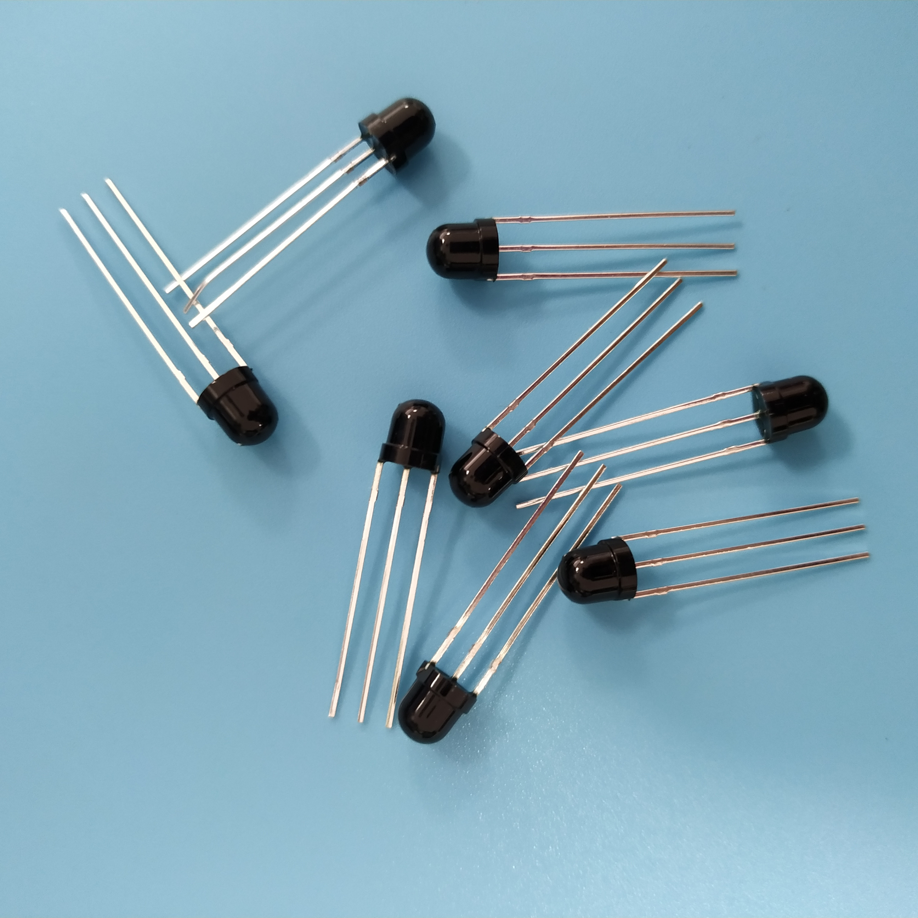
A custom infrared component is agreed on paper long before it is agreed in a factory. The drawing is signed, the sample is approved, and then the question that decides whether the assembly line runs is asked: when does it arrive, and in what form. Those two questions are usually treated as logistics. In practice they are decided much earlier, by choices made during the drawing review.
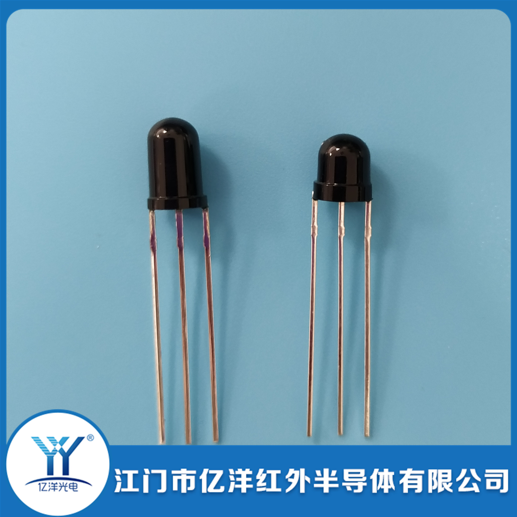
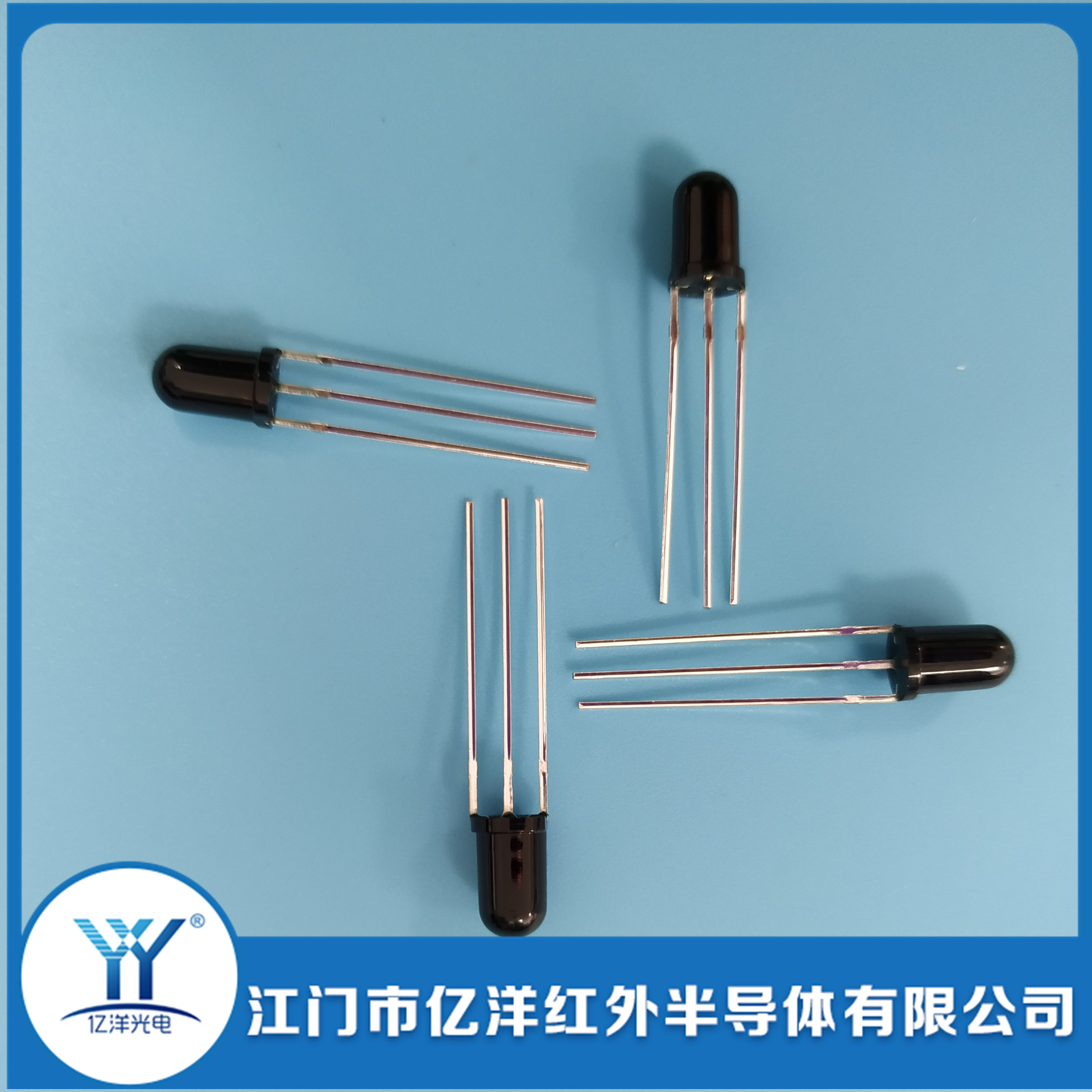
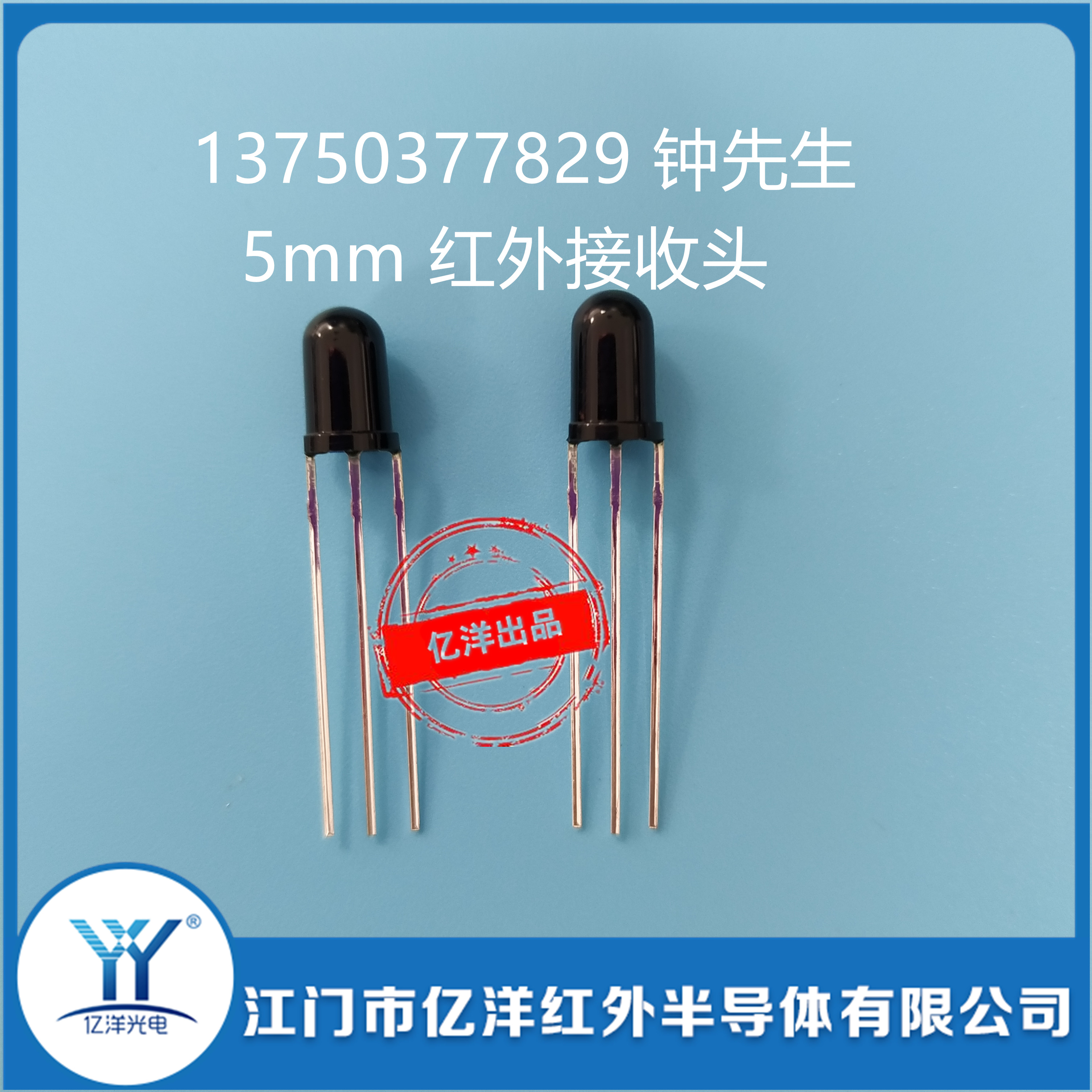
Jiangmen City Yiyang Infrared Semi-conductor Co., Ltd (Yiyang Optoelectronics YY) has packaged infrared emitters, photodiode receivers and receiver heads in Jiangmen, Guangdong for over 13 years, with a daily capacity of 600K pieces, a dust-free packaging workshop and its own packaging production line, exporting to more than 40 countries, with 5mm emitters, 5mm round receivers and SMD patch receivers among the regularly stocked families. The recurring friction in custom orders is not manufacturing capability. It is a schedule slip caused by an incomplete drawing, or a reel that does not fit the feeder on the customer's line.
This article walks the order from drawing to reel: the five stages, what each one needs from the customer, the difference between an in-stock shipment and a custom build, and how packaging is chosen against the assembly equipment rather than against habit.
The Five Stages of a Custom Order
Every custom request moves through the same sequence, whether it is a single changed lead length or a new package. Knowing the sequence is what makes a schedule predictable, because the delays are almost always at the handover points between stages.
| Stage | Customer supplies | Factory returns | Typical duration |
|---|---|---|---|
| 1. Drawing and requirement review | Drawing or written requirement; application; annual quantity; assembly method | Feasibility confirmation, open questions, quotation | Days, not weeks — the questions are technical, not commercial |
| 2. Sampling | Approval to build samples; shipping address | Sample parts built to the agreed drawing | Part of the 3–7 working day custom window |
| 3. Sample approval | Test results on the customer's own fixture; accept or revise | Revised drawing if needed | Customer-side; the most common source of schedule slip |
| 4. Production scheduling | Purchase order; quantity; required date | Production slot, shipping documents | Standard models 1–3 days in stock |
| 5. Packaging and dispatch | Packaging form: reel, bag or bulk; label requirements | Packed goods, packing list | Within the production window |
Two observations follow. First, the factory-controlled part of the timeline is short — standard in-stock models ship within 1–3 days and custom specifications are typically completed within 3–7 working days. Second, the variable part is the interface: an incomplete drawing adds a round trip at stage 1, and a slow sample evaluation adds an open-ended delay at stage 3.
1. Drawing Review: What Makes a Custom Request Move Fast
A custom request that can be quoted and built without a follow-up question has certain things in it. The list is short and unglamorous.
- The device identity — emitter, photodiode receiver, receiver head, or a pair. A request that says "infrared sensor" cannot be quoted.
- Package family and body size — 3mm, 5mm round, square, bridge-type head, SMD or through-hole.
- The customization items, each with a figure — lead length in millimetres from a stated datum, pitch, bend angle, epoxy colour, target wavelength, target power ratio.
- Photoelectric targets — the figures that must not change while the mechanical items are customized.
- Assembly method — hand soldering, semi-automatic insertion, automatic insertion, or reflow. This single line decides the packaging.
- Annual and first-order quantity — what separates a lead-frame modification from a mold.
- Any environmental requirement — ambient light, operating temperature band, wash or cleaning exposure.
The one item most often missing is the assembly method, and it is the one with the widest consequences. A part destined for an automatic insertion head has to be supplied in a form the head can grip, with lead co-planarity inside a tolerance the feeder can accept. A part destined for hand soldering has none of those constraints and can be supplied in a bag at lower cost. Without that line, the factory either guesses or asks, and either way the schedule moves.
2. Sampling: What a Sample Actually Proves
A sample does not prove that production will be identical. It proves that the drawing can be built and that the optical result lands where the design expects. Both are worth confirming, and both are confirmed on the customer's fixture rather than on a datasheet.
| What to test on the sample | Why it matters more than the datasheet |
|---|---|
| Fit in the actual housing or probe | Lead length, bend and epoxy height only matter against the real mechanical envelope |
| Optical output at the working distance | A figure measured at the factory fixture is not the figure at 3mm or 8mm in the product |
| Behaviour under the product's ambient light | Filtered versus unfiltered bodies diverge most in the field, not on the bench |
| Soldering result at the actual process temperature | Reflow profile and wave-solder conditions stress the epoxy in ways a hand test does not |
| Insertion on the actual equipment | Feeder grip, lead straightness and reel pitch are only proven on the line |
Small quantities of samples can be provided for testing, with the customer covering shipping. That arrangement is most useful when the sample is treated as a process trial rather than an optical check — running twenty parts through the real line tells you more than measuring one part on a bench.
Sampling from a drawing
Where the requirement is a new lead form or a special angle, sampling is done from the drawing rather than from a catalogue part. That is a different activity from picking a stock sample: the drawing has to be complete enough to build from, and the accepted sample then becomes the reference the production run is checked against. A drawing-based sample that is approved without a measurement record is a weak reference, because there is nothing to compare the production run to.
3. In-Stock Versus Custom: Where the Timing Difference Comes From
The published figures are simple: standard models in stock ship within 1–3 days, and in some product families standard stock ships within 24 hours; customized specifications are usually completed within 3–7 working days. The reason for the gap is worth understanding, because it tells you which requests can be pulled forward.
| Order type | What happens | Typical timing | How to shorten it |
|---|---|---|---|
| Standard in-stock model | Pick, inspect, pack, dispatch | 1–3 days; 24 hours for regularly stocked lines | Confirm the model against the stock list before ordering |
| Standard chip and package, changed lead form | Fixture change, build, optical inspection, pack | Within the 3–7 working day custom window | Provide a complete drawing at the first contact |
| Changed epoxy colour or wavelength bin | Material or chip lot selection, build, sort, inspect | Within the 3–7 working day custom window | Accept a wider bin if the design allows it |
| New mold | Tooling manufacture, first articles, approval, then production | Longer than the custom window, driven by tooling | Confirm that a lead-form change cannot meet the requirement first |
The practical consequence: a request that only changes lead length, lead form or epoxy colour is inside the normal custom window and needs no special arrangement. A request that changes the package geometry leaves that window entirely. Deciding which one you actually need is the highest-leverage step in the whole schedule.
4. Packaging: Reel, Bag or Bulk
Packaging is usually specified by habit — whatever the previous supplier used. It should be specified by the feeding equipment, because the packaging is the interface between the component and the machine that places it.
| Packaging form | Feeds | Best for | Constraints |
|---|---|---|---|
| Tape and reel (carrier tape) | Automatic SMT placement machines; automatic insertion equipment where a taped form is supported | SMD parts; volume through-hole assembly with automated feed | Requires the feeder and reel size to match; pocket geometry must suit the part |
| Anti-static bag, 1000pcs per bag | Manual or semi-automatic assembly; hoppers that accept bulk | Through-hole DIP parts; small and medium volumes | Parts must be counted and handled at the line; ESD-safe handling required |
| Moisture-proof vacuum packing | Any, after opening | SMD parts that must survive storage and shipping humidity | Mounting recommended within 24 hours of opening; reseal for long-term storage |
| Bulk / custom pack | Customer-specific | Where the line uses a bespoke hopper | Needs agreement on count, orientation and labelling |
Why SMD parts arrive on reel and DIP parts arrive in bags
The split follows the assembly technology rather than a preference. SMD emitters and receivers are placed by a machine that picks from a tape pocket, so the carrier tape, the pocket dimensions and the reel pitch are all part of the delivery specification. Through-hole DIP parts are usually inserted by hand or by an insertion head that takes parts from a loose or stick feed, so an anti-static bag of 1000 pieces is the natural unit.
Large-volume through-hole orders can be supplied with customized tape packaging for automatic insertion equipment, which is worth asking about when insertion is automated. The point of the tape is not protection but feed rate: an insertion head fed from tape runs at a consistent rate, while a bag-fed line needs an operator or a bowl feeder and introduces orientation errors.
Moisture and the 24-hour rule
SMD parts are supplied in vacuum moisture-proof tape packaging, and mounting is recommended within 24 hours after opening. The reason is the epoxy body: it absorbs moisture from the air, and that moisture flashes to steam during reflow, which can crack the package or delaminate the lead frame. The rule is not a formality. A reel opened on Friday and run on Monday has been exposed to a weekend of plant humidity.
Long-term storage should stay sealed and moisture-proof. Where a partial reel must be kept, resealing with desiccant is the minimum, and the exposed tape should be rewound rather than left hanging.
5. Reflow Tolerance and What It Implies for Handling
The SMD packages, including the 2-pin SMD patch emitter, are built to survive short-time reflow with a peak temperature up to 260°C, with high-temperature exposure limited to about 10 seconds. That figure is a ceiling, not an operating point, and it constrains the process around the part rather than the part itself.
| Process item | Requirement | Why |
|---|---|---|
| Reflow peak temperature | Up to 260°C, exposure limited to about 10 seconds | The epoxy and the internal chip attach are rated to that ceiling |
| Number of reflow passes | Minimize; a second pass re-stresses the package | Each cycle adds cumulative thermal stress |
| Through-hole soldering | Iron at or below 300°C, contact under 3 seconds; wave solder for volume | Prolonged contact damages the chip and the epoxy |
| Storage before use | Sealed, dry, light-proof | Lead oxidation and epoxy yellowing both degrade performance |
| Drive current | Rated 20mA per chip; pulses permitted within the design | Overdrive raises junction temperature and shifts wavelength |
Two of these interact with packaging decisions in ways that are easy to miss. A part shipped on tape and stored sealed reaches the reflow oven in the intended condition; the same part shipped in an open bag and stored on a shelf may not. And a part that is reflowed twice — once on a sub-assembly, once on the main board — accumulates stress the datasheet does not describe, because the rating is written for one exposure cycle.
6. Batch Consistency and Final Inspection
The last variable in the schedule is the one that shows up after delivery: whether the shipment behaves like the sample. Consistency comes from inspection at the end of the line rather than at the start of it.
Yiyang Infrared runs packaging in a dust-free workshop with inspection of photocurrent, dark current and spectral response on finished components, and with chip sorting by wavelength and output before packaging. The way those parameters are read on a datasheet is covered in the emitter specification guide and the photodiode receiver specification guide. The practical meaning for a buyer is that the delivered batch has been screened on the same parameters the design depends on, and that tightening a bin is a sorting instruction rather than a process change.
For an order that runs across several shipments, consistency also depends on drawing from a continuous production lot. A second shipment built from a different chip lot will meet the same specification and still differ slightly in measured output. Where the design is sensitive to that difference, stating the requirement up front — same lot where possible, tighter bin where not — avoids a calibration exercise on arrival.
Order Readiness Checklist
- Device type and package family stated, not implied.
- Each customization item carries a figure and a tolerance, with the measurement datum named.
- Assembly method identified — hand, semi-automatic, automatic insertion, or reflow.
- Packaging form selected against the feeding equipment, with reel size and pocket orientation confirmed where tape is used.
- Photoelectric targets stated, so the mechanical changes are bounded.
- Sample quantity and evaluation plan agreed, including a process trial rather than only a bench measurement.
- First order and annual quantity given, which decides lead modification versus mold.
- Required delivery date stated with the order type, so it can be scheduled against the 1–3 day stock or 3–7 working day custom window.
- Storage and handling plan confirmed — the 24-hour mounting rule for SMD, sealed storage for both.
- Label and packing list requirements given, since re-labelling after dispatch is not possible.
Ordered So the Line Does Not Wait
The gap between a custom infrared order that lands on schedule and one that does not is rarely manufacturing capacity. It is a drawing that omitted the assembly method, a sample evaluated only on a bench, or a reel that did not fit the feeder. All three are settled before the purchase order, and all three cost nothing to settle at that point.
Yiyang Infrared supplies standard in-stock models in 1–3 days and custom specifications typically within 3–7 working days, with tape-and-reel packaging for automatic placement, anti-static bags at 1000 pieces for through-hole parts, and customized carrier tape for high-volume automatic insertion. Send the drawing, the assembly method and the required date together, and the schedule can be quoted against a complete requirement rather than a partial one.
Related reading in this series: lead length, pitch and epoxy customization, matching an emitter to a photodiode, and the 660nm/905nm optical pair and SMT process guide. For supplier evaluation, see how to choose a reliable infrared component supplier; for company and factory background, about Yiyang Infrared; purchasing questions are collected in the FAQ, and the company news archive carries product and capacity updates.